Main menu
You are here
Alarm system
[last updated: 2020-01-30]
go to: FONA cell phone module
go to: alarm system - GetWired
-----
- System Configuration:
The current breadboard configuration uses the following modules: - Sensor interface Arduino:
- Arduino nano,
connected to the alarm-status panel,
and also reads proximity/intrusion sensors (GMC & stairwell)
and also outputs signals to the FONA for various action,
Currently programmed with outsidePanel-03.ino - Fona cellphone module
- At this time, this is the "base/home" station.
It reads signals from the sensor interface arduino
and sends SMS signals to sysAdmin (me) indicating events and status.
It also responds to SMS signals to take actions or send status updates. - Current implementation uses an Arduino Mega 256: (project name): FONA-2
- alarm-status panel
- These are small panels outside whichever doors,
(initially just the basement door),
with a red/green LED showing alarm status,
blinking red = activated, solid green = alarm off - LED's on this panel are controlled by the sensor interface Arduino
- Annunciators:
- Screamers:
These are the "rape alarm" modules which put out a warbling high freq alarm.
They're available on ebay for $2 - $5. - Not currently implemented ...
- Future configurations may use some of the following modules:
- Base station:
- LED's:
red/grn alarm-set status
red/grn alarm-trigger status
red for each sensor
red/grn setup & HB
red/blu xmit/rcv - PB's:
set alarm
reset all? - window in case to view LED's on FONA module
- Front door panel:
- doorbell
speaker
microphone
bicolor LED
red = alarmed
green = alarm clear
yellow LED = key-press
RGB LED: red = key error
camera? - Keypad Module
- located inside (at least) front door, and perhaps also inside back and basement doors
- when someone comes into the house while the alarm is activated,
they have some time to enter a valid code into this keypad module
before the alarm annunciates a break-in - contains 12-button keypad and indicating LED's
- a red/green LED indicating alarmed/safe status
- a yellow LED that blinks when a key is pressed on the keypad
- a red LED that blinks when an incorrect keypad entry is received
- an arduino to read the keypad and control the LED's
- keypad module arduino sends signals to keyboard monitor
- Current software rev is: keypad05a.ino
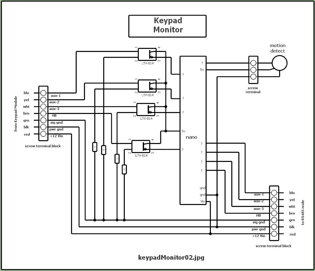
- Keypad Monitor
- keypad monitor arduino sends signals to RS485 node, to be relayed to base station computer
---------------------------------------
.
.
.
eof

