Main menu
You are here
Load Cells & Wheatstone Bridges
[last updated: 2019-01-17]
3d printing home page
Load Cell Electronics
-----
- Load cells:
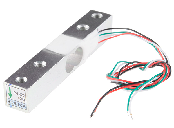
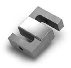
- A load cell is a component used to measure force or weight. It does this by being configured in a physical apparatus that will bend it or compress it (if ever so slightly) when weight/force is applied.
- The amount of bend is measured using strain gauges.
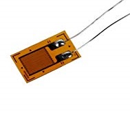
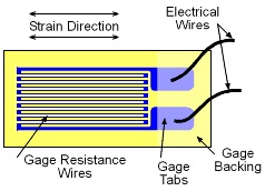
- Strain Gauges are resistive elements that increase their resistance if stretched, and decrease resistance if compressed/shortened.
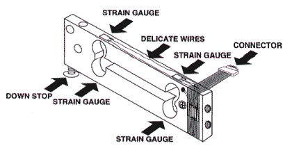
- They are mounted/glued to a flat bar or beam (to create the load cell).
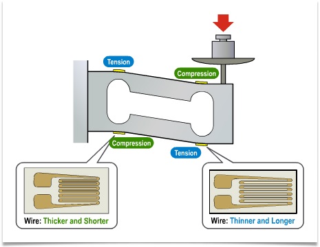
- A traditional load cell has 4 strain gauges, two on top, and two on the bottom.
- When the beam is bent down on both ends, one of the strain gauges on the top, and one on the bottom (see diagram) will be stretched/elongated, and their resistance will increase.
- At the same time, the other 2 strain gauges, one on top and one on the bottom, will be compressed/shortened, and their resistance will decrease.
- The amount of resistance change is tiny, so it's necessary to do some clever electronics to get enough signal to have any accuracy. This is done with a Wheatstone Bridge.
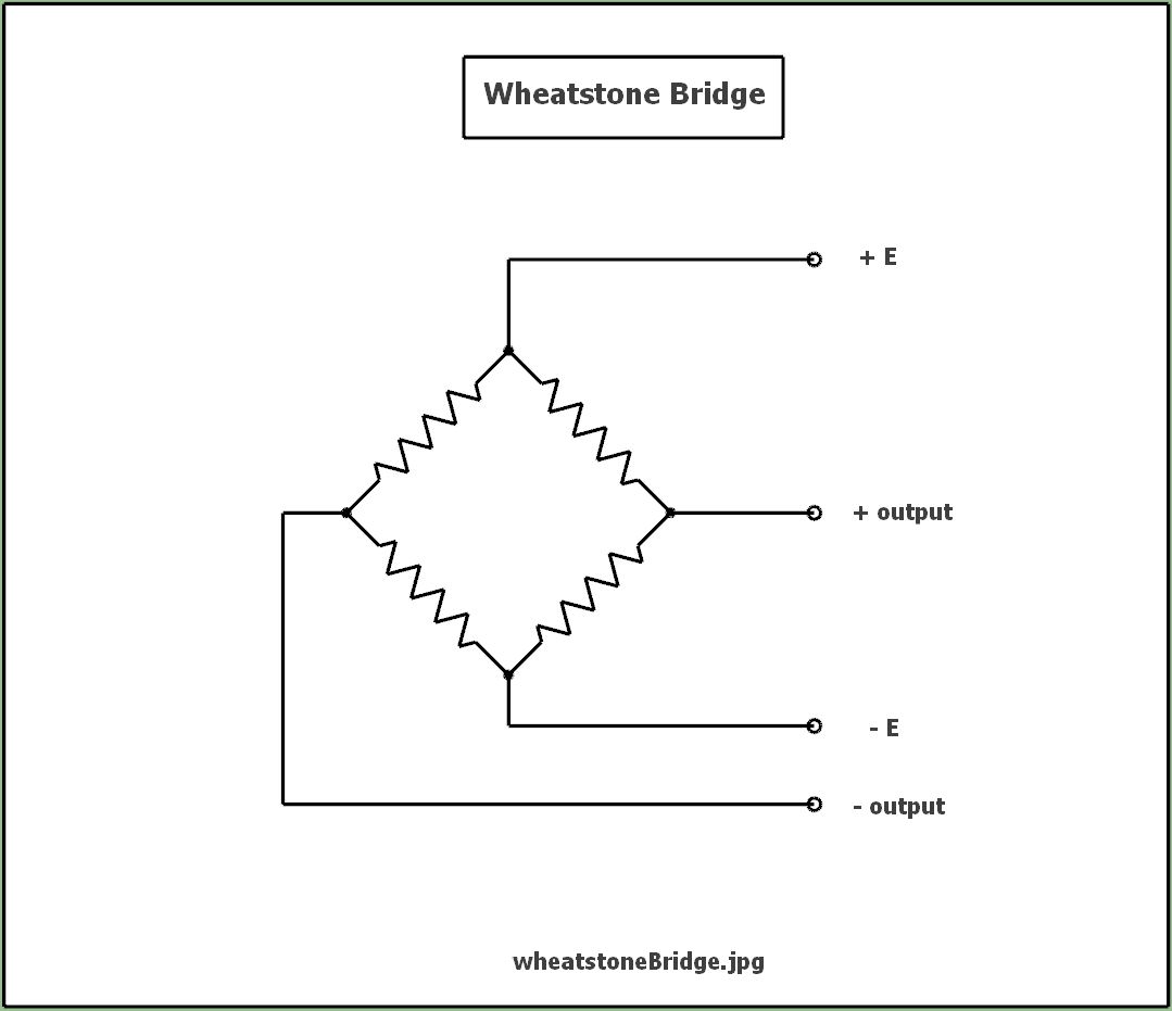
- A Wheatstone bridge:
- ... is a connection configuration that allows combining (to increase total signal) the tiny resistance changes of the 4 strain gauges on a load cell.
- When the strain gauges are connected as shown (resistive elements), all 4 gauges move the signal in the same direction when force is applied. That is, the total change in resistance (the signal) when using a Wheatstone bridge with an applied weight/force, will be 4x the magnitude of the change in resistance from just one strain gauge.
- At the same time, the absolute magnitude of the signal will still be centered closely to zero, making electronic amplification easier and more accurate.
- A Wheatstone bridge has 4 terminals:
- Two (opposite) connections for applied voltage, called Exitation voltage (usu. E+ & E-). It's necessary for this voltage source to be very well regulated and constant.
- Two (opposite) connections for the net signal output of the bridge.
To be usable, the output signal must be highly amplified with a high gain, low noise amplifier (see: HX711).
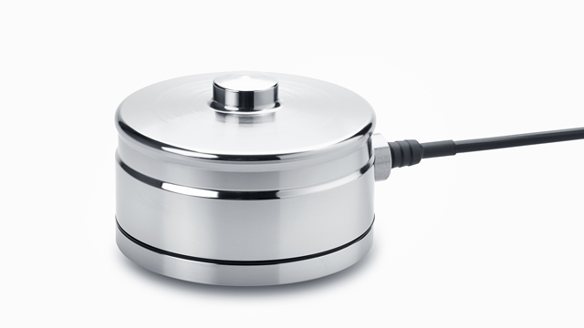
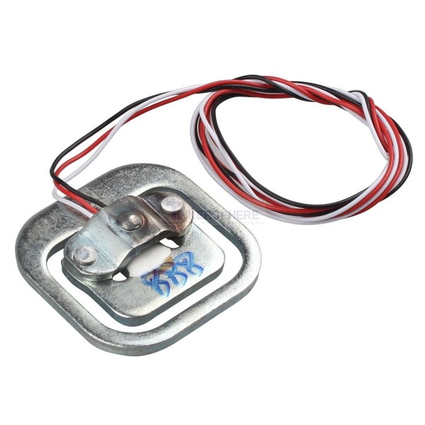
- Compression type load cells (button types and bathroom scale types) must be built so that strain gauges are still mounted on a part of the structure that bends, as strain gauges do not measure compression directly.
.
.
.
eof
