Main menu
You are here
nRF24-1 Project Details
[last updated: 2021-04-04]
(go to:) nRF24 home page
(go to:) nRF24 Simplest
-----
- Hardware:
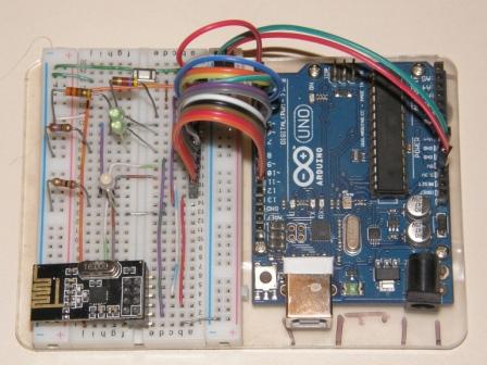
- General configuration: each node is composed of an nRF24L01 module controlled by an Arduino Uno.
- The Arduino communicates to the nRF24 module via SPI
- Each node also has several LED's for indicating status:
bi-color setup
bi-color xmit/rcv mode
message successfully received (on sender node)
message send failed (on sender node)
some message received (on receiver node) - each node also has a pushbutton
- hardware pinouts
- Software/Operation:
- (go to:) nRF24 General Software
- (go to:) nRF24-1 software/operation configuration
- (go to:) nRF24-1 programs
- Summary/Status:
- As of program rev. 16, everything works. Range is better than some of the online reports had led me to believe, even with on-board antenna with no mods. Testing the range of your transmission is a sketchy process. Results are not consistent. That is, upon initiating a 'send message' by pushing the PB, sometimes I get success after like 2 seconds, but sometimes, without moving position, it takes 15sec.
In line-of-sight outside, I can get about 90' before missing every send. Through the house and 1935 lath-and-plaster walls, it's much worse, successful with maybe 20' separation. (see antenna discussion) - Also tried the power adapter boards with built-in 3.3v regulators, supposedly able to supply sufficient 3.3v current for more reliable operation than the 50ma available from Uno 3.3v output.
As usual, results difficult to evaluate. Best guess is that it's better, though how much better is impossible to quantify.
need to add supply caps to schematic

