Main menu
You are here
SPI: home page
[last updated: 2025-05-12]
SPI software
SPI breadboard trial
SPI vs. i2c
-----
- Description:
- SPI (Serial Peripheral Interface) is a synchronous serial data protocol used by microcontrollers for communicating with each other or with one or more peripheral devices.
- Maximum range is generally considered to be about 10', though lower clock speeds give more range, and bus driver circuitry can extend it dramatically, reportedly up to 100m or more.
- There is one master/controller and may be multiple slaves/peripheral devices.
- If there are multiple slaves, they are differentiated and managed by each having its own Chip Select line.
- That's the theory, at least, though I have not yet figured how to implement it in practice...
- A given communication (data transfer) is always initiated by the master/controller.
- Using the Arduino SPI.h library, a communication from the master to the slave is done by executing:
- SPI.transfer([byte of data to be sent]);
Each such transfer consists of a single byte of data, though many SPI.transfer(...) 's can be done in sequence under program control for transferring bigger chunks of data.
- A single byte will be returned from slave to master with each byte that gets sent from master to slave.
- If you wish to use the byte of data that is returned from slave to master, do this:
- byte dataRcvd = SPI.transfer([byte of data to be sent]);
-----------------------------------------
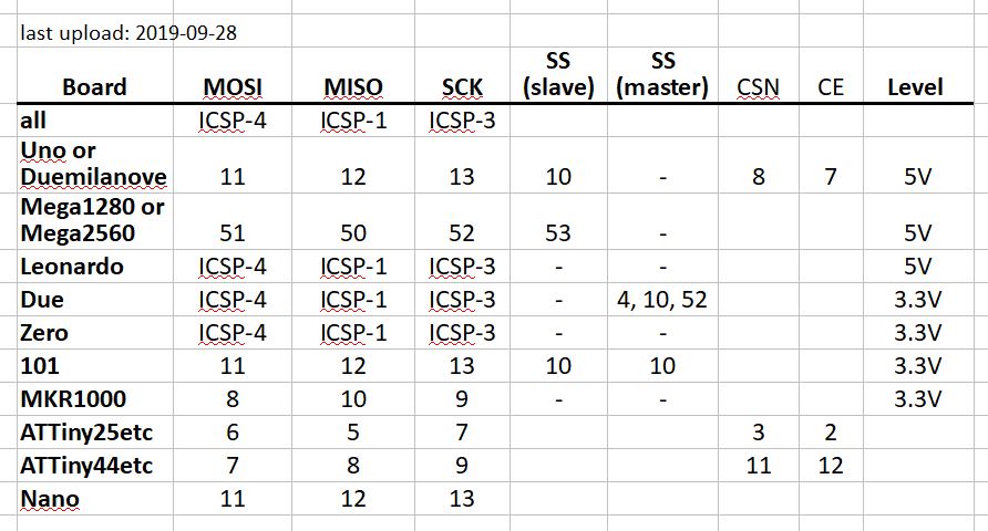
- Hardware:
- 3 lines common to all peripherals:
MOSI - Master Out, Slave In (COPI - Controller Out, Peripheral In)
MISO - Master In, Slave Out (CIPO - Controller In, Peripheral Out)
SCK - Serial Clock - and 1 line for selecting which peripheral device you're communicating with:
SS - Slave Select (or CS - chip select) - low to select, high to ignore - MOSI/COPI line of master MCU connects to MOSI/COPI of slave
MISO/CIPO of master connects to MISO/CIPO of slave
SCK of master connects to SCK of slave - A dedicated output from the master connects to the SS of the slave. It will be controlled by the master software.
- That is, if you have more than one SPI device on the same MCU, then connect the MOSI lines together, same for MISO and SCK,
then specify a separate SS line for each device. - 3 lines common to all peripherals:
- Arduino models often have (different) hard-wired (ie. not changeable) pin assignments for SPI signal lines.
--------------------------------------------------------------------------------------------------------------
- https://www.arduino.cc/reference/en/language/functions/communication/spi/
- For more information on programming etc. (link to:) See Arduino.cc page
.
.
.
eof
Powered by Drupal