Main menu
You are here
Current sensors
[last updated: 2025-05-09]
-----
- Linear Hall Current Sensor Module
- ACS758LCB-050B-PFF-T
CJMCU-758
sku: 498152-d8>KP
Banggood $3.99 - Features:
- excellent noise performance with advanced amplifier and filter design techniques
- integrated shield reduces capacitive coupling, and prevents offset drift in high voltage applications
- total output error improvemed with gain and offset trim over temperature
- Ultra-low power loss: 100 μΩ internal conductor resistance
- high galvanic isolation
- Electrical characteristics (X050):
- operating voltage: 3V - 5 V (max 8 V)
- output voltage: VCC/2
- operating current: 13.5 mA (max)
- max output current: 3 mA
- bandwidth: 120 KHz
- detection current range: ±50 A
- linearity: 40 mv/A
- working temperature: -40 to 150 C
- size: 37mm x 18mm
- Operation Notes:
- The relationship between voltage output and current input:
VOUT = VOUT(Q) + Vsens x I VOUT(Q) is the quiescent output voltage, which is VCC/2, which is the output voltage when there is no input. Vsens is a sensor-sensitive scale, also known as a coefficient. I is the current flowing from IP+ to IP-.
For example, suppose the sensor model is 050B, VCC is 5V, and I current is 10A, then the output is 5V / 2+40mV/A x10A=2.9V.
- The relationship between voltage output and current input:
------------------------------------------------------------------
- ACS758LCB-050B-PFF-T
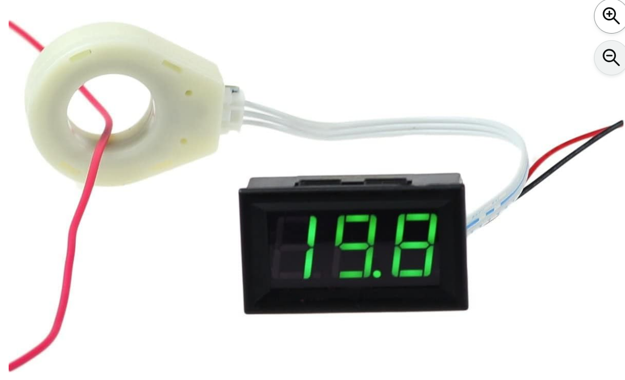
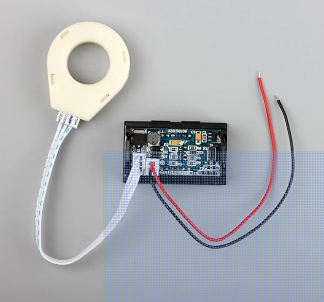
- Bayite 100A Volt/Amp meter:
- with Hall Effect Sensor Transformer
- BYT-VAM-033
ASIN: B01DDQM6Z4 -
-
- Measurement Range: + -100A
Measuring Accuracy: + -1%
Resolution: 0.1A
Working current: 7-15mA
Power supply: DC 5-120V
Overall Dimensions: 48mm*29mm*23mm
Cutout size: 45.5mm*25.5mm
Sensor hole diameter: 19mm
Operating temperature: -4°F - 140°F (-20°C - 60°C)
Reverse Polarity Protection:Yes
Electrically isolated from circuit being measured - Meter and sensor loop are paired at factory. Do not swap sensor loops between different meters.
- If you have a low amperage signal to read, loop the wire being measured through the sensor several times. This will increase the signal proportional to the number of loops. For example, if your current signal is only 0.2 A, then loop the wire through the sensor 10 times and the signal will be 10X stronger and will measure as 2.0 A.
- Negative current measurement is indicated by a decimal point at far right of the display.
- Operation:
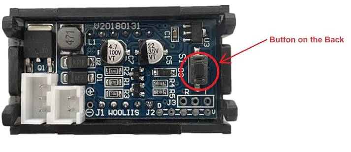
- PB operation:
"press the PB" means holding it slightly more than just click and release, perhaps about 1 sec.
press PB once, screen displays "A", then displays current measurement.
press button again, display reads "A U", then displays alternating current and voltage measurements (note: current reading typically flickers in this mode).
press button again, then display reads "U" and shows voltage (voltage of power supply feeding the meter). - Resetting/calibrating:
Remove current sensing wire, or ensure no current is flowing
Press and hold the PB for >2sec, then release
Display should read "CCC" to indicate successful calibration.
If the display reads "IFF", then there is no connection between the meter and the sensing loop. - Obnoxious that the PB is only accessible from the back, so if you mount the meter in a panel as it's designed to be mounted,
you can't actuate the PB for like calibration.
Will need to solder a jumper parallel wires on the switch on the board (looks doable) to bring it out to the front panel where I'll mount it beside the meter.
- PB operation:
------------------------------------------------------------------
- Pololu 2452
- Uses ACS711 sensor
range: +/- 15.5 A
Vcc 3.3 - 5v
Output analog voltage proportional to current,
and centered on Vcc/2
------------------------------------------------------------------
- Uses ACS711 sensor
- Pololu 4040
- Uses ACS724LLCTR-2P5AB
+/- 2.5 A range
------------------------------------------------------------------
------------------------------------------------------------------
- Uses ACS724LLCTR-2P5AB
- Links/refs:
- from hacktronics:
Description:
The Allegro™ ACS758 family of current sensor ICs provides economical and precise solutions for AC or DC current sensing. Typical applications include motor control, load detection and management, power supply and DC-to-DC converter control, inverter control, and overcurrent fault detection.
The device consists of a precision, low-offset linear Hall circuit with a copper conduction path located near the die. Applied current flowing through this copper conduction path generates a magnetic field which the Hall IC converts into a proportional voltage. Device accuracy is optimized through the close proximity of the magnetic signal to the Hall transducer. A precise, proportional output voltage is provided by the low-offset, chopper-stabilized BiCMOS Hall IC, which is programmed for accuracy at the factory.
High level immunity to current conductor dV/dt and stray electric fields, offered by Allegro proprietary integrated shield technology, provides low output voltage ripple and low offset drift in high-side, high voltage applications.
The output of the device has a positive slope (>VCC / 2) when an increasing current flows through the primary copper conduction path (from terminal 4 to terminal 5), which is the path used for current sampling. The internal resistance of this conductive path is 100 μΩ typical, providing low power loss.
The thickness of the copper conductor allows survival of the device at high overcurrent conditions. The terminals of the conductive path are electrically isolated from the signal leads (pins 1 through 3). This allows the ACS758 family of sensor ICs to be used in applications requiring electrical isolation without the use of opto-isolators or other costly isolation techniques.
The device is fully calibrated prior to shipment from the factory. The ACS758 family is lead (Pb) free. All leads are plated with 100% matte tin, and there is no Pb inside the package. The heavy gauge leadframe is made of oxygen-free copper.
- from hacktronics:
.
.
.
eof
Powered by Drupal