Main menu
You are here
ESP8266 HiLetgo Node MCU
[last updated: 2021-09-28]
ESP32 & ESP8266 home page
-----
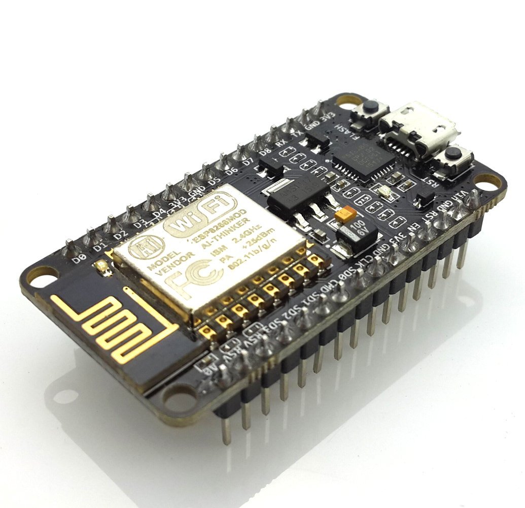
- HiLetgo ESP8266 NodeMCU CP2102 ESP-12E
This dev board has a ESP8266 microprocessor plus a wifi module.
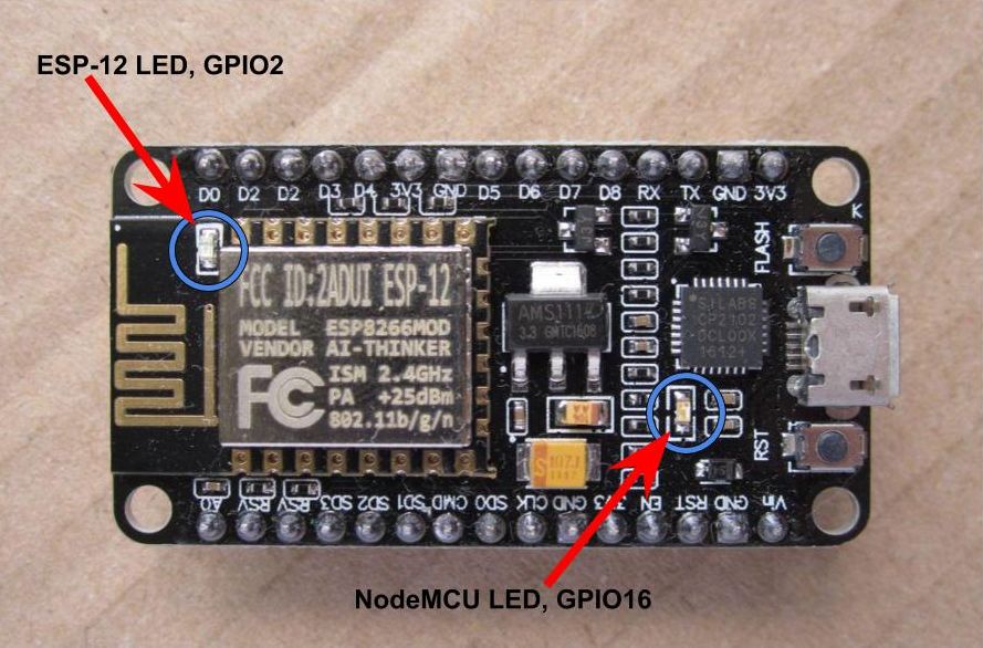
It has a micro-USB port for programming (Arduino IDE). - There are two on-board blue LED's, controlled by GPIO2 and GPIO16.
Logic is inverted, ie. when the output is LOW, the LED is On.
(Picture from: https://lowvoltage.github.io/2017/07/09/Onboard-LEDs-NodeMCU-Got-Two) - Setup/Operation:
- 1. Download the Arduino IDE, the latest version.
- 2. Install the IDE
- 3. Set up your Arduino IDE as: Go to File->Preferences and copy the URL below to get the ESP board manager extensions:
http://arduino.esp8266.com/stable/package_esp8266com_index.json- (placing the http:// before the URL lets the Arduino IDE use it...otherwise it gives you a protocol error.)
Click OK.
Note: If you already have some other URL listed, add a comma and add the 8266 URL on the next line. - 4. Go to Tools > Board > Board Manager> Type "esp8266" . Click Install for the Community esp8266.
- 5. Set up your chip as:
Tools -> Board -> NodeMCU 1.0 (ESP-12E Module)
Tools -> Flash Size -> 4M (3M SPIFFS)
Tools -> CPU Frequency -> 80 Mhz
Tools -> Upload Speed -> 921600
Tools-->Port--> (whatever it is)
However: These defaults were automatically loaded, except my system used an upload speed of 115200 - I skipped steps 6 - 7, and just did step 8 to upload the Blink example program, and it worked fine.
- 6. Download and run the 32 bit flasher exe at Github(Search for nodemcu/nodemcu-flasher/tree/master/ at Github)
github.com/nodemcu/nodemcu-flasher/tree/master/Win32/Release
Or download and run the 64 bit flasher exe at:
github.com/nodemcu/nodemcu-flasher/tree/master/Win64/Release - 7. In Arduino IDE, look for the old fashioned Blink program. Load, compile and upload.
---------- - 8. Go to FILE> EXAMPLES> ESP8266> BLINK to load the Blink program into the IDE
click Upload. Took forever to compile, may have been hung, clicked something or waited long enough and it finished successfully.
- If error: "esptool.FatalError: Failed to connect to ESP8266: Timed out waiting for packet header“.
It means that your ESP8266 is not in flashing/uploading mode.
To resolve, see instructions:
https://randomnerdtutorials.com/how-to-install-esp8266-board-arduino-ide/ - If error: "could not open port, permission denied“.
It likely means you are not a member of the group that owns the port, usually the dialout group.
(go to:) dialout permissions - Going further:
- To build a web server to display sensor readings, you can read the following tutorials:
- ESP8266 DHT Temperature and Humidity Web Server (Arduino IDE)
https://randomnerdtutorials.com/esp8266-dht11dht22-temperature-and-humid... - ESP8266 DS18B20 Temperature Web Server (Arduino IDE)
https://randomnerdtutorials.com/esp8266-ds18b20-temperature-sensor-web-s... - To program your ESP8266 using MicroPython, see this tutorial: ESP32/ESP8266 MicroPython Web Server – Control Outputs
https://randomnerdtutorials.com/esp32-esp8266-micropython-web-server/
- ESP8266 DHT Temperature and Humidity Web Server (Arduino IDE)
- Questions?
- Are high outputs +5v? or 3.3v? - have not tested, but surely they are 3.3v
- Can inputs take 5v? - best guess is definite NO
- What are default pin states on powerUp? or after reset?
My test on E8 showed GPIO:
0, 1, 2, 3, 9, 10, ... HIGH
... LOW
and 12, 13, 14, 15, 16, ... High Z
(with, at this time, 4 & 5 unknown as being programmed in use.)
- Gotcha:
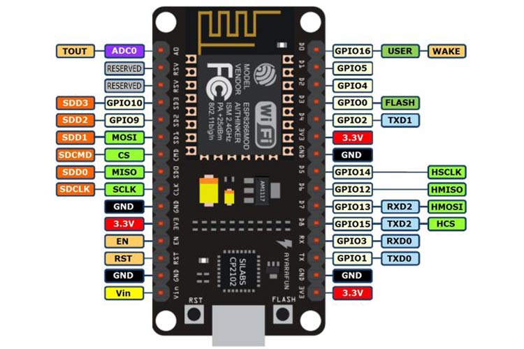
- There are pin ID's printed on the circuit board. However they are different from the ID's that are used in a program to access the IO pins.
For example, the pin labeled on the board as "D0" is shown on the pinout diagram as "GPIO16", and will be accessed by your Arduino IDE program as "16",
pinmode(16, OUTPUT) or digitalWrite(16, HIGH)
--------------------------------------------------------------------------- - There are pin ID's printed on the circuit board. However they are different from the ID's that are used in a program to access the IO pins.
- To build a web server to display sensor readings, you can read the following tutorials:
.
.
.
eof


