Main menu
You are here
MosFets
[last updated: 2025-08-14]
MPPT charge controllers
-----
- Mosfets have three terminals: Source, Drain, and Gate.
The Source is connected towards the negative voltage
and the Drain is connected towards the positive voltage - Mosfets can be used as switches, full-on to full-off, or as virtual voltage-controlled resistors.
In a switch mode, they can be fed with a PWM gate signal, resulting in an effectively variable/controllable output. - Two main categories of mosfets:
- Note: there are other classifications as well, but these are the main two.
Every mosfet will have some value in each of these two categories.- Either enhancement or depletion
- Enhancement:
Normally Off, turned On by proper Gate signal - Depletion:
Normally On, turned Off by proper Gate signal
- Enhancement:
- Either n-channel or p-channel
This specifies the polarity of the "proper Gate signal"- n-channel:
The Source must be more negative than the Gate .
ie. the Gate must be more positive than the Source. - p-channel:
???The Source must be more positive than the Gate
------------------------------------------------------------------------------------
- n-channel:
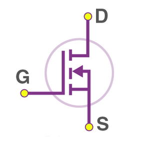
- This results in 4 combinations:
Each form has its own unique circuit/schematic symbol. However there is latitude in the exact symbol used. For example, there is an internal zener diode in mosfets that can be shown on the symbol, but usually is not.
These are the symbols I find most commonly:- n-channel enhancement
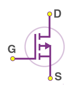
- p-channel enhancement
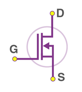
- n-channel depletion
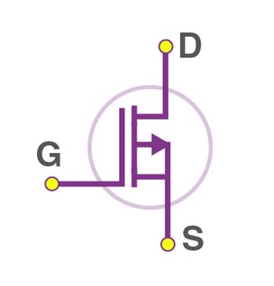
- p-channel depletion
- n-channel enhancement
------------------------------------------------------------------------------------
- Either enhancement or depletion
- Operation:
- To keep this explanation simple, I'll just consider n-channel enhancement mosfets.
- Recall enhancement mosfets are off until they're turned on by a proper gate signal.
- A "proper gate signal" means proper polarity and value/magnitude.
- Magnitude is always in relation to Source voltage (which will be different in different circuit configurations).
In fact, the gate voltage level is often symbolized as: Vgs = Vg - Vs
Further, Vgs must be greater than the Threshold voltage of your part. This parameter, VTH
is listed in your mosfet's data sheet and will be different for two different mosfet models. - Polarity is determined by whether you have a "p-channel" or an "n-channel"
If n-channel, VGS must be greater than Vs, by at least the Vth amount.
If p-channel, VGS must be less than Vs, by at least the Vth amount.
- Magnitude is always in relation to Source voltage (which will be different in different circuit configurations).
------------------------------------------------------------------------------------
- Links/Refs:
- testing guide: https://www.youtube.com/watch?v=aSU0aQHAP9Y
- semiconductor theory of enh mosfets: https://nerdsdostuff.com/electronic_circuits/enhancement-mosfet-construc...
- ok, but not much to work with: https://www.electronicsforu.com/technology-trends/learn-electronics/n-ch...
- not much actionable: https://www.tutorialspoint.com/basic_electronics/basic_electronics_mosfe...
- mostly worthless: https://hereyup625.weebly.com/enhancement-n-channel-mosfet.html
-------------------------------------- - device specs:
- IRF9540 specs: https://components101.com/mosfets/irf9540-mosfet-pinout-datasheet-equiva...
- IRF9540 specs: https://www.alldatasheet.com/datasheet-pdf/pdf/68329/IRF/IRF9540.html
IRF9540 on Amazon: https://www.amazon.com/s?k=irf9540n+p-channel+mosfet&crid=27A10DJZKR7MX&...
-------------------------------------- - bootstrap circuits:
- excellent - but S & D reversed in diagram?: https://www.youtube.com/watch?v=wtMOtueXNJQ
- https://www.youtube.com/watch?v=izUDxwgpzt8
- https://www.youtube.com/watch?v=zcQV_ZpK1W8&t=194s
- not bad: https://www.youtube.com/watch?v=dZrtVSY7iJ4
- same guy, diff vid: https://www.youtube.com/watch?v=ArH33idCHOc
--------------------------------------
- drivers-info:
- https://www.kynix.com/Blog/how-to-select-right-mosfet-drivers.html
gate driver output current must be enough to charge up the gate capacitance... - pretty good: https://www.youtube.com/watch?v=8swJ_Bnsgl4&t=34s
interesting circuit schematic at 08:39
basic transistor driver schematic at 09:43
recommends LMG1210 driver at 10:05, which includes bootstrap capability
however is only available in SMD
however youtube author has a breakout PCB available?
even more complicated theory later...
--------------------------------------
- https://www.kynix.com/Blog/how-to-select-right-mosfet-drivers.html
- drivers-sources:
- https://www.amazon.com/High-Power-Adjustment-Electronic-Controller-Brigh...
- https://www.amazon.com/Onyehn-Mosfet-Button-Arduino-Raspberry/dp/B07GLNC...
- https://www.amazon.com/5PCS-IR2104PBF-Driver-HIGH-IR2104/dp/B0CL4JSFPT/r...
- https://www.amazon.com/IR2101PBF-Electronic-Component-Precision-Performa...
- https://www.kynix.com/Blog/how-to-select-right-mosfet-drivers.html
gate driver output current must be enough to charge up the gate capacitance...
--------------------------------------
- constant current circuits:
- The current source operates because of the fact that the collector current in a transistor circuit is Β times the base current.
This is independent of the collector voltage, provided that there is sufficient voltage to drive the current through the load device in the collector. - generic constant current theory: https://electronicmanufacturingservice.org/constant-current-source-a-com...
- transistor circuit - image: https://www.electronics-notes.com/images/transistor-active-current-sourc...
- https://www.analog.com/en/resources/design-notes/using-a-linear-regulato....
- https://www.bristolwatch.com/ccs/index.htm
- https://www.instructables.com/A-Neat-Little-Variable-Constant-Current-Ad...
- https://electronics.stackexchange.com/questions/689670/how-to-supply-a-c...
- https://www.allaboutcircuits.com/technical-articles/the-basic-mosfet-con...
very basic mosfet circuit, but most of discussison is around ic design - https://www.youtube.com/watch?v=kRusWWNyOOI
- https://forum.arduino.cc/t/constant-current-source-picking-a-mosfet/676830
interestingg discussion, some nuggets perhaps - https://www.youtube.com/watch?v=ngco8UAYj3o
- good, w/ calculations: https://www.scribd.com/document/388798041/MOSFET-Constant-Current-Driver
- https://www.electronics-tutorials.ws/transistor/fet-current-source.html
good basics of mosfet operation
--------------------------------------
- The current source operates because of the fact that the collector current in a transistor circuit is Β times the base current.
------------------------------------------------------------------------------------
- Addendum...
- p-ch have higher on-resistance than n-ch
- Using an N-channel MOSFET as a high-side switch is possible, but it requires the gate voltage to be significantly higher than the source voltage to turn it on, which can complicate the circuit design. Generally, P-channel MOSFETs are preferred for high-side switching due to their simpler operation.
- IRF mosfets need ca 10V at the gate to fully turn on.
IRL mosfets need ca 5V at the gate to fully turn on. - A MOSFET is like a variable resistor. The Gate-Source voltage controls the Drain-Source Resistance.
When there is no voltage between the Gate-Source , the Drain-Source resistance is very high, effectively an open circuit. - N-channel: The Source is connected to ground. To turn it on, apply a voltage to the Gate. To turn it off, ground the Gate.
- P-Channel: The Source is connected to Vcc. To turn it on, connect the Gate to ground. To turn it off, connect the Gate to Vcc.
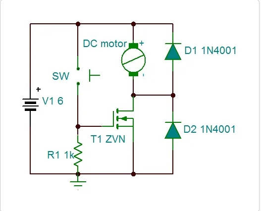
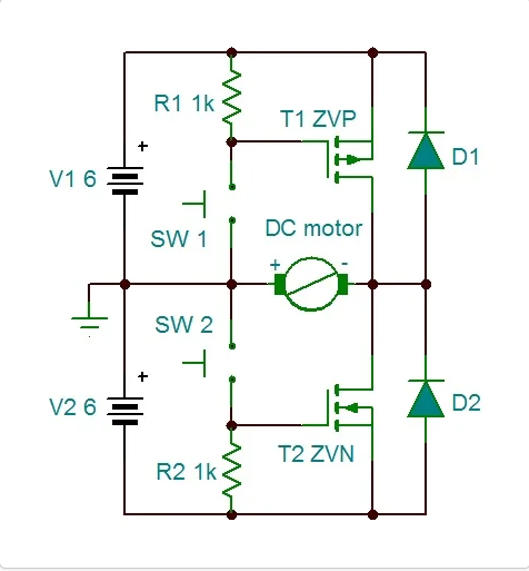
------------------------------------------------------------------------ - Circuits:
- Motor Drivers:
.
.
.
eof
Powered by Drupal