Main menu
You are here
IR Remote Reciever
[last updated: 2025-01-20]
IR Remote - home page
-----
- This page is in process ...
- The heart of an IR receiver is the sensor:
Adafruit 157 - TSOP38238 IR receiver:
NOTE: different TSOP models have different pinouts. Check your datasheets.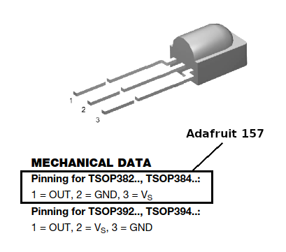
- The Adafruit 157 contains a bandpass filter that only responds to (passes) approx 35-40 KHz IR pulse trains,
and toggles its output active if they are received.- Recall this is the carrier frequency of the IR pulse train.
- IR detectors are reverse logic:
- they output LOW (0V) if they detect a 38KHz carrier,
and they output HIGH (5V) if they do not.
------------------------------------------------------------------
- The Adafruit 157 contains a bandpass filter that only responds to (passes) approx 35-40 KHz IR pulse trains,
- Test/Demonstrate operation of IR sensor:
- First breadboard an IR receiver chip and demonstrate
that its output toggles when it receives 38 KHz signals from an existing remote. - This can be done without an MCU, since the IR receiver chip output can directly drive an indicator LED:
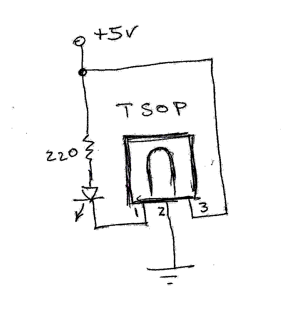
This was successful, with the output LED flashing whenever an IR remote clicker was aimed at the receiver chip and a button was pressed on the remote.
Tested with Philips, Vizio, and a Universal remote. - Or it can be done With an MCU, which I did successfully with Arduino program: IR_LEDsensorTest.ino
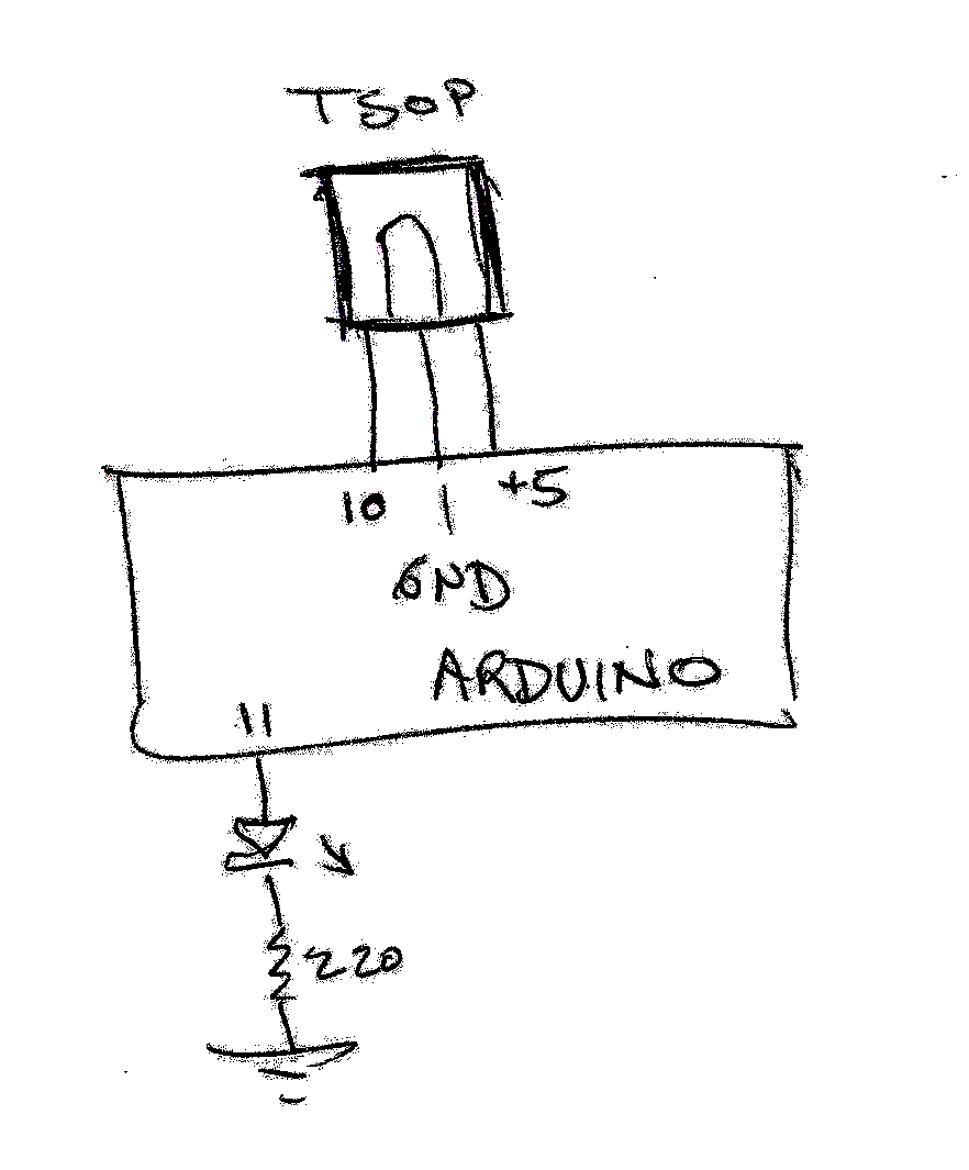
This program does not "decode" any signals, it merely reads the Arduino input that is connected to the IR receiver output, and flashes the Arduino output LED if a signal (low active) is received from the IR receiver chip.
------------------------------------------------------------------
- First breadboard an IR receiver chip and demonstrate
- Getting Raw Data from a sensor:
- External circuitry (Arduino or other) monitors the receiver output pin (which goes low-active whenever there is a 38 KHz carrier), and measures the length of the 38 KHz pulses.
Recall a given button press on the remote will send out some number of pulses, of different lengths, separated by spaces (during which no 38-KHz carrier is sent).
The number of pulses sent for each button press is different for different manufacturer protocols, often 16 or 32 pulses. - While simply reading a digital input (ie. Arduino code: digitalRead(pinNum); ) worked just fine in the above test to verify IR receiver chip function,
when all you needed to do was detect the presence of the carrier, which was indicated by the sensor output going low,
if you instead want to measure the lengths of the pulses, which are on the order of a few hundred microseconds,
then the Arduino digitalRead command is way too slow to measure accurately. - "Getting raw data" is the process of measuring the lengths of the bursts of 38 KHz pulses, and the length of the spaces in between the bursts.
The total pattern of (however many) bursts, of variable lengths, plus the length of spaces in between them,
constitute the unique identity of the button that was pressed. - Raw Data is a list/sequence of numbers. Each number is the number of microseconds in a pulse or space.
So the set of numbers that constitutes "raw data" for a given key press will start with the length of the first/leading space, then the first pulse length,
then the next space length, and so on.
random, unedited, addendum material in this section ...
- When you use a program to read "raw data" from the IR remote after having pressed a button on the remote,
you will get a list of times, usec durations, for pulses and spaces.- (Recall that the "pulses" are times when the IR LED in the remote is outputting a 38KHz carrier, and the IR sensor output pin will be active low,
and the "spaces" are times when the IR LED in the remote is NOT outputting a carrier, ie. is off.)- The raw data will start with a space (OFF time), then will alternate between pulses (ON time) and spaces.
- The first, starting space is discarded, being the time from the last data pulse from the last button press (or from the start of the program)
until the first data pulse. - Following the discarded initial space, there will be some number of pulses and spaces that constitute the start sequence.
The specifics of this sequence will be different for different manufacturers/protocols, but one possibility is eg.- a single pulse of a specific length (usec), followed by a single space of some length.
- After the start sequence, the "actual" data that corresponds to the specific button press will be listed.
The data will consist of the measured lengths (usec) of the pulses and spaces.
There will be significant variability in the measured numbers, due to the fact that accurately measuring microseconds is non-trivial, especially for an inexpensive Arduino.
Variability can easily be 5 - 10%.
But examining the data will clearly show that the numbers will cluster around 2 or three average values.
------------------------------------------------------------------
- External circuitry (Arduino or other) monitors the receiver output pin (which goes low-active whenever there is a 38 KHz carrier), and measures the length of the 38 KHz pulses.
- Software to get raw data:
- I have found 3 Arduino methods to do that:
- Adafruit method:
- uses clever, brute-force programming to directly/accurately measure the usec pulse widths.
Does not use added libraries. - Outputs a list of off and on times, in microseconds.
Then outputs the same data, formatted in Arduino code,
for direct copy and paste into an Adafruit sending sketch. - My sketch name: ... Ada_IRreceive_01b
- Regardless that this method is effective, and brilliant, from a programming perspective,
and in fact could be used as a programming tutorial for rather esoteric code techniques,
IMO it's way more complicated that needed, esp. given the availability of libraries that do all this work for you.
---------------------------------------------------------------
- uses clever, brute-force programming to directly/accurately measure the usec pulse widths.
- IRLib2 library:
- This library can tell you which manufacturer's protocol is being used on an IR pulse that it receives.
---------------------------------------------------------------
- IRremote library:
- from https://techzeero.com/arduino-tutorials/ir-receiver-and-remote-with-ardu...
- My sketch: IRremote_recv-02.ino (basic code came directly from the website).
However many more sketches available in IDE --> File --> Examples --> IRremote - Note this program does not output raw data.
In fact, the library routines do a full decode of the raw data,
and the program outputs a single code, hex and/or decimal, of the decoded raw data
that corresponds to the button pressed.
------------------------------------------------------------------
------------------------------------------------------------------ - Adafruit method:
- ... proceed to decode raw data ...
------------------------------------------------------------------
eof