Main menu
You are here
nRF24 antennas
[last updated: 2017-06-20]
(go to:) nRF24 home page
-----
- Improve the antenna:
- Test protocol:
two identical boards, same sketch loaded,
programmed w/ PB to initiate send, and LED to indicate received;
test and move successively farther apart until communication fails. - With onboard PCB antenna (A-0):
successful at 40' line-of-sight or through 1 wall (1930's lathe & plaster), did not test further;
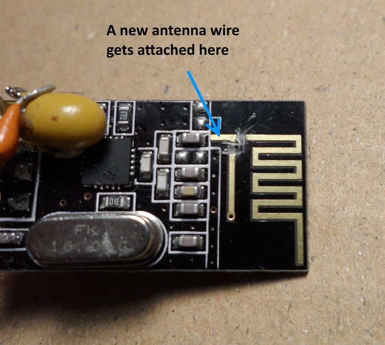
started failing at 25' through 2 walls (transmissions were successful about 1/2 the time). - First mod (A-1) added a vertical whip. 3.25" to the end of the PCB antenna. This was calculated by someone online so that the total of this added whip and the onboard PCB antenna would total the 4.92" ideal for a full wavelength. It did seem to improve things, but only ever so slightly.
- Next (A-2) I cut 2 traces to remove the PCB antenna from the circuit,
and added a 4.92" whip (see link below). Results clearly better, and with a whip on both sender and receiver, I got 40' range (max that I could test inside the house), even through a couple of walls - better, still not as good as I'd expected from other people's results.
- Next (A-3), using same traces cut as in A-2, I built the dipole per link below. It may have been the best, but see below.
- Antenna test summary:
- Results of individual tests (with a given combination of antennas) was not highly repeatable.
Sometimes they worked, other times not as well.
All my tests were done indoors, taking one of the modules to various places in the house, though I tried to pick and stick with specific spots.
But even then, sometimes a transmission would succeed immediately, sometimes not until after retries, and sometimes I'd have to re-test a few times before I'd get the ack from a successful transmission. - Bottom line, it was a tough judgement call to quantify the results even into digital pass/fail.
- My general impression, however, is that all three of the antenna mods worked better than the A-0 PCB antenna, but we're only talking a few extra feet at best.
- That said, later testing revealed (what I should have expected) that these little antennas are very directional, and seem to have strongest signal strength perpendicular to the board. Such that, when sender and receiver were "aimed" thusly at each other, reception was noticeably better.
- Results of individual tests (with a given combination of antennas) was not highly repeatable.
- Future test plan:
- I suspect that using a lot of retries limits the resolution/discrimination of test results, so at some time I'll get back to it and reduce retries and test again.
- I'll also try taking the modules outside where test conditions can be simple distance of line-of-sight.
- Dipole antenna theory (see link below) suggests tweaking the length to compensate for reactance, based on diameter of antenna wire thickness.
--------------------------
- Test protocol:
- References:
- Dipole antenna (incl. where to cut traces): (link to:) Instructables
- Scanner sketch: (link to:) maniacbug
- Whip addition to PCB antenna (with statements of theoretical ideal length): (link to:) YouTube
- Dipole antenna theory: (link to:) wiki
.
.
.
eof
