Main menu
You are here
MAX485 Module
[last updated: 2024-09-08]
RS485 home page
RS485 Software
RS485 on rPi for GMC GUI
-----
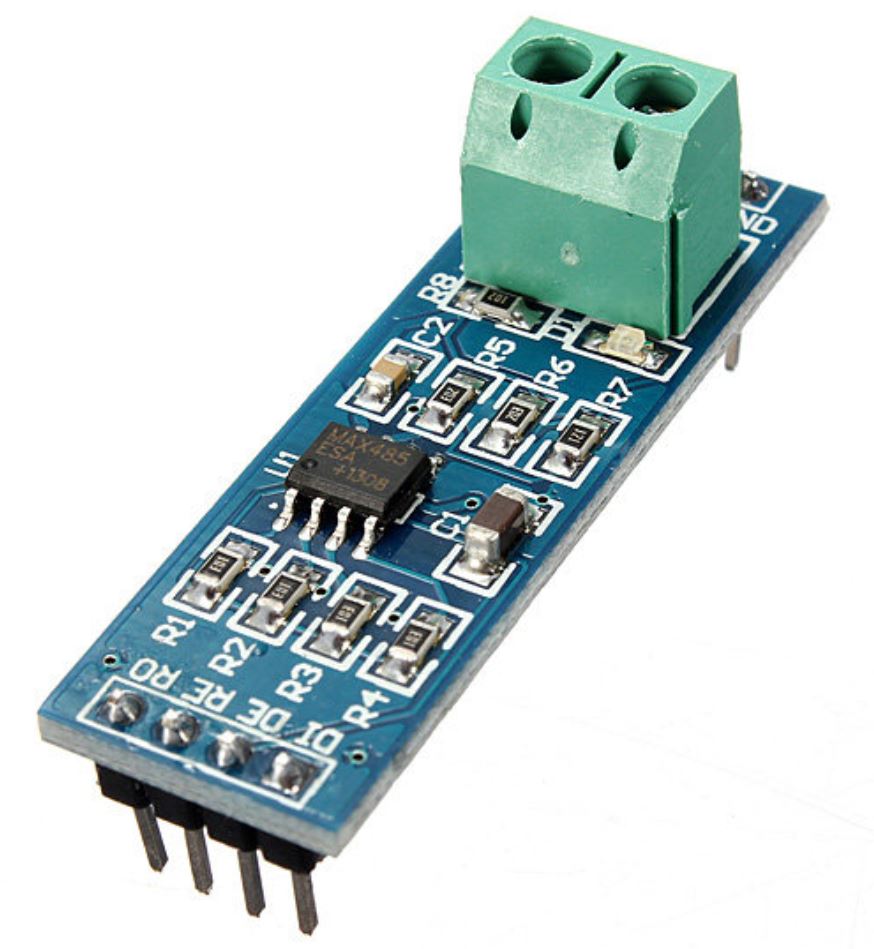
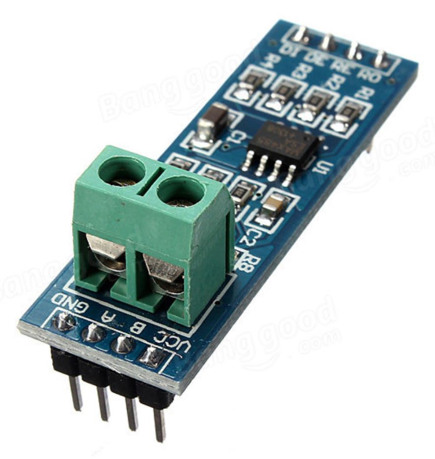
- Lots of implementations are available, but I'm using these MAX485 TTL-RS485 converters, cheaply available on the web.
- Hardware notes:
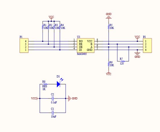
- Bus wiring: each bus line should have a resistor, 'A' has a pull-up (20k) to Vcc, 'B' has a pull-down (20k) to gnd, to put the lines into a known state when no transmission is coming across the bus.
- In addition, there should be a resistor (120 ohm) between A and B, but strictly speaking only at the ends of the bus line.
- All these resistors are included in the MAX485 module.
The YourDuino site says R7 on the MAX485 module, which is the 120 ohm resistor between A & B, should be removed if you have a multi-slave system, and only retained on the Last module on the bus. - Serial I/O are 5v.
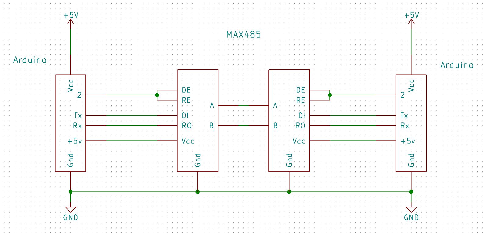
DI: "Driver Input" data into MAX from MCU to be sent out on the bus
RO: "Receiver Output" data received by MAX from bus that is being sent back to MCU - DE & RE are enable pins:
DE is "drive enable" and must be HIGH to Transmit
RE is "receive enable" and must to LOW to Receive
If you connect them together, then feed them from a single microcontroller output,
High = Tx
Low = Rx - Level shifting:
- I'm doing a project using RTS485 MAX modules,
and the MCU's I'm using are Arduino Teensy and ESP32,
both of which are 3.3v devices. - The 3.3v outputs from the MCU for DE/RE and Tx output to DI should be sufficient to trigger the 5v max inputs.
However the RO output from the MAX at 5v would destroy the MCU 3.3v inputs, so needs to be level shifted.
... working on the schematic ...
- I'm doing a project using RTS485 MAX modules,
.
.
.
eof


